null
close
close
close

Model 468: Operation and Maintenance

The 468 and O’Brien turn your jetter into a high-powered cleaning system. Below you can get acquainted with the features and operation of the 468.

Model 468

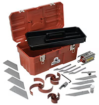
The Spartan Tool 468 root cutter fits pipes 4-10” in diameter, delivering 800-2000 PSI of operating pressure at a 10-15 GPM flow rate. It connects to 3/8, ½”, ¾”, or 1” hose and has an operating distance of 400 feet. The 468 is self-propelled with removable, low-profile skids and can be positioned into lines without having to enter the manhole. This drain cutter’s instant lube-fitting allows for easy lubrication without disassembly, and comes with a dedicated toolbox and leader hose (no need to remove the skids to remove the hose).

How it Operates

After the skid and cutter blade have been attached to the unit, attach the high pressure hose and the placement unit. Next, lower the root cutter into the pipe or the manhole and position it with cutter blade facing in the direction of travel. (If possible, cutting should always be done against the flow to allow debris to be carried back to the working manhole.) Start jetter engine and turn on water pressure momentarily to allow root cutter to enter the line several feet. Then, turn off pressure and position hose guide/guard (tiger tail) at pipe entrance. Tie the safety rope of the hose guide/guard to the jet or clamp in place, and mark the hose top of manhole entrance with white waterproof tape.

Begin the cleaning operation by running the engine at low PSI, never exceeding 2000 PSI. You can increase the PSI to the maximum level as you enter the cleaning cycle. Feed the root cutter hose slowly into pipe so cutter can cut obstructions and the blade can rotate freely (a jammed blade could cause jet hose twist and damage). Slack in the hose indicates that the root cutter has encountered an obstruction. When this occurs, immediately pull back on the hose by hand then gradually feed hose forward to allow the root cutter to cut into and through the obstruction. Make sure you have good footing while performing the above action.

If the root cutter does not penetrate the blockage after several minutes, you may have encountered a lateral or collapsed pipe. At this point, other options should be considered, such as removing the root cutter and introducing a camera to visually inspect the pipe, as continued operation without penetration can damage the root cutter and/or could cause it to lock-up in the pipe. A blockage has been penetrated when no slack can be felt or seen in the hose. If this occurs, slowly feed the root cutter a few feet further up the pipe to ensure that you are through the blockage. For every 2-3 feet of blockage, pull root cutter back towards the manhole to clear the pipeline of debris (the white tape marking will mark how far cutter is from entry). Do not pull unit all the way into manhole at this time, but reduce water pressure and flow to root cutter to prevent debris from washing into another pipe. If debris does not seem excessive, you may be able to proceed further than 2-3 feet until the line is cleaned.

However, if the amount of debris is excessive on the first run, pull root cutter toward pipe entrance after turning down pressure to allow debris to build up at the bottom of the manhole. Then, turn off water pressure and engine, and remove root cutter from manhole by hand. Clean debris from both the unit and the manhole. Once this is finished, reinsert the hydraulic cutter into the line and repeat this procedure until the pipe is clean.

When the job’s complete, retrieve the root cutter and remove it from the hose. If root cutter will not be used again within a 6 hour period, remove the cutter blade and with the supplied special grease coupler attached to a grease gun, pump light weight grease into the orifice grease fitting (the motor shaft will be turned by the grease as this is done). When grease can be seen at the hose connection the root cutter can be stored. In freezing conditions, be sure to keep root cutter motor unit warm or service with grease immediately. As grease may become thick in extreme cold (and if warming is not possible), service root cutter motor with S.A.E. #10 motor oil. You can do this by first orienting the motor so the shaft is pointing down, then slowly pouring oil into the hose connection at the jet nozzle while turning the motor shaft in a clockwise direction (with provided “T” wrench) as viewed from the hose connection end. When oil is forced out of the orifice grease fitting, oiling is complete.

Cutter Blade Selection and Attachment

Saw blades for the 468 are available in 4, 6, 8, and 10 inch sizes. These blades (with the exception of the 4” saw) allow ½” clearance in the pipeline and the skid assemblies are designed smaller than the cutter blades to allow unit to pass through the opening cut by the saw blade. See table below for what size cutter and skid should be used in pipe cleaning applications:

PIPE SIZE SKID SIZE CUTTER SIZE
4" 4" or 6" 4"
6" 4" or 6" 4" or 6"
8" 6" or 8" 6" or 8"
10" 8" 10"

The 468 root cutter offers a compact design of cutter blades and ease of changing that is not offered by competitor's units.

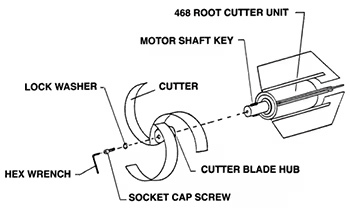
The blade is driven by a key located on the motor shaft. The hub of the cutter blade is fitted with a keyway slot, which, when placed in line with the shaft key, will allow the cutter to slide down the shaft. A washer stop is provided at the end of the hub, and the cutter should be pushed onto this stop. Using the allen wrench provided, place one of the stainless steel socket head screws from the kit and tighten securely. This screw prevents the cutter from pulling off the shaft when retracting the root cutter from the line.

This method of assembly allows the 468 to be made more compact in design and offers ease of cutter change as all the work is done at the front of the unit. The hub is provided with clearance between the motor face to allow for the prying-off of stubborn cutter blades if rust occurs. Note it is a good practice to place a light film of oil on the motor shaft and in the cutter blade hold after each use to prevent rust formation.

Model 468 Root Cutter Diagram 1

Proper Orifice Selection and Skid Mounting

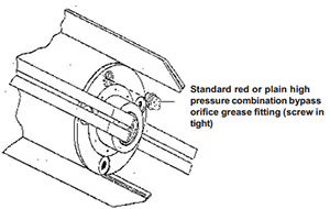
The 468 is supplied with two special bypass orifice grease fittings. One style must be selected and screwed into the jet head for proper root cutter operation. The orifice fittings are color coded, one red (standard) and the other plain finish (high pressure). If your jet operates from 800 PSI (57 bars) to under 1500 PSI (140 bars), select the red (standard) orifice. If your jet operates at 1500 (103 bars) to 2000 PSI (140 bars) or more, use the plain orifice.

Model 468 Root Cutter Diagram 2

800 to < 1500 PSI (57 to < 140 bars) - Use red (standard) orifice

1500 to < 2000+ PSI (103 to 140+ bars) - Use plain finish orifice

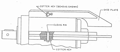
Our hydraulic root cutter skid mounting design is unique, as plate runners are mounted to the body shell by means of four removable pins which are locked in place by cotter keys. Therefore, the main motor will never need to be removed from the body shell to change skid sizes! By attaching the skid plates in this manner, the hose end of the plates are projected downward and rearward, offering a large angle projection over twice that of conventional skid units.

This provides greater protection to root cutter removal in the even an offset or dropped line is encountered. Plus, skid plates are stamped with pipe size for easy selection. Note that skid plates on the body shell should not be intermixed. To simplify skid plate removal and change, the snipping off of the end of the cotter key is recommended. Use only new cotter keys for assembly (standard size).

Model 468 Root Cutter Diagram 3

The 468 and O’Brien turn your jetter into a high-powered cleaning system. Below you can get acquainted with the features and operation of the 468.

Spartan Tool 468 Root Cutter

The Spartan Tool 468 root cutter fits pipes 4-10” in diameter, delivering 800-2000 PSI of operating pressure at a 10-15 GPM flow rate. It connects to 3/8, ½”, ¾”, or 1” hose and has an operating distance of 400 feet. The 468 is self-propelled with removable, low-profile skids and can be positioned into lines without having to enter the manhole. This drain cutter’s instant lube-fitting allows for easy lubrication without disassembly, and comes with a dedicated toolbox and leader hose (no need to remove the skids to remove the hose).

How it Operates

After the skid and cutter blade have been attached to the unit, attach the high pressure hose and the placement unit. Next, lower the root cutter into the pipe or the manhole and position it with cutter blade facing in the direction of travel. (If possible, cutting should always be done against the flow to allow debris to be carried back to the working manhole.) Start jetter engine and turn on water pressure momentarily to allow root cutter to enter the line several feet. Then, turn off pressure and position hose guide/guard (tiger tail) at pipe entrance. Tie the safety rope of the hose guide/guard to the jet or clamp in place, and mark the hose top of manhole entrance with white waterproof tape.

Begin the cleaning operation by running the engine at low PSI, never exceeding 2000 PSI. You can increase the PSI to the maximum level as you enter the cleaning cycle. Feed the root cutter hose slowly into pipe so cutter can cut obstructions and the blade can rotate freely (a jammed blade could cause jet hose twist and damage). Slack in the hose indicates that the root cutter has encountered an obstruction. When this occurs, immediately pull back on the hose by hand then gradually feed hose forward to allow the root cutter to cut into and through the obstruction. Make sure you have good footing while performing the above action.

If the root cutter does not penetrate the blockage after several minutes, you may have encountered a lateral or collapsed pipe. At this point, other options should be considered, such as removing the root cutter and introducing a camera to visually inspect the pipe, as continued operation without penetration can damage the root cutter and/or could cause it to lock-up in the pipe. A blockage has been penetrated when no slack can be felt or seen in the hose. If this occurs, slowly feed the root cutter a few feet further up the pipe to ensure that you are through the blockage. For every 2-3 feet of blockage, pull root cutter back towards the manhole to clear the pipeline of debris (the white tape marking will mark how far cutter is from entry). Do not pull unit all the way into manhole at this time, but reduce water pressure and flow to root cutter to prevent debris from washing into another pipe. If debris does not seem excessive, you may be able to proceed further than 2-3 feet until the line is cleaned.

However, if the amount of debris is excessive on the first run, pull root cutter toward pipe entrance after turning down pressure to allow debris to build up at the bottom of the manhole. Then, turn off water pressure and engine, and remove root cutter from manhole by hand. Clean debris from both the unit and the manhole. Once this is finished, reinsert the hydraulic cutter into the line and repeat this procedure until the pipe is clean.

When the job’s complete, retrieve the root cutter and remove it from the hose. If root cutter will not be used again within a 6 hour period, remove the cutter blade and with the supplied special grease coupler attached to a grease gun, pump light weight grease into the orifice grease fitting (the motor shaft will be turned by the grease as this is done). When grease can be seen at the hose connection the root cutter can be stored. In freezing conditions, be sure to keep root cutter motor unit warm or service with grease immediately. As grease may become thick in extreme cold (and if warming is not possible), service root cutter motor with S.A.E. #10 motor oil. You can do this by first orienting the motor so the shaft is pointing down, then slowly pouring oil into the hose connection at the jet nozzle while turning the motor shaft in a clockwise direction (with provided “T” wrench) as viewed from the hose connection end. When oil is forced out of the orifice grease fitting, oiling is complete.

Cutter Blade Selection and Attachment

Saw blades for the 468 are available in 4, 6, 8, and 10 inch sizes. These blades (with the exception of the 4” saw) allow ½” clearance in the pipeline and the skid assemblies are designed smaller than the cutter blades to allow unit to pass through the opening cut by the saw blade. See table below for what size cutter and skid should be used in pipe cleaning applications:

PIPE SIZE SKID SIZE CUTTER SIZE

4"

4" or 6"

4"

6"

4" or 6"

4" or 6"

8"

6" or 8"

6" or 8"

10"

8"

10"

The 468 root cutter offers a compact design of cutter blades and ease of changing that is not offered by competitor's units.

The blade is driven by a key located on the motor shaft. The hub of the cutter blade is fitted with a keyway slot, which, when placed in line with the shaft key, will allow the cutter to slide down the shaft. A washer stop is provided at the end of the hub, and the cutter should be pushed onto this stop. Using the allen wrench provided, place one of the stainless steel socket head screws from the kit and tighten securely. This screw prevents the cutter from pulling off the shaft when retracting the root cutter from the line.

This method of assembly allows the 468 to be made more compact in design and offers ease of cutter change as all the work is done at the front of the unit. The hub is provided with clearance between the motor face to allow for the prying-off of stubborn cutter blades if rust occurs. Note it is a good practice to place a light film of oil on the motor shaft and in the cutter blade hold after each use to prevent rust formation.

Spartan Tool 468 blade attachment

Proper Orifice Selection and Skid Mounting

The 468 is supplied with two special bypass orifice grease fittings. One style must be selected and screwed into the jet head for proper root cutter operation. The orifice fittings are color coded, one red (standard) and the other plain finish (high pressure). If your jet operates from 800 PSI (57 bars) to under 1500 PSI (140 bars), select the red (standard) orifice. If your jet operates at 1500 (103 bars) to 2000 PSI (140 bars) or more, use the plain orifice.

Spartan Tool 468 orifice

800 to < 1500 PSI (57 to < 140 bars) - Use red (standard) orifice

1500 to < 2000+ PSI (103 to 140+ bars) - Use plain finish orifice

Our hydraulic root cutter skid mounting design is unique, as plate runners are mounted to the body shell by means of four removable pins which are locked in place by cotter keys. Therefore, the main motor will never need to be removed from the body shell to change skid sizes! By attaching the skid plates in this manner, the hose end of the plates are projected downward and rearward, offering a large angle projection over twice that of conventional skid units.

This provides greater protection to root cutter removal in the even an offset or dropped line is encountered. Plus, skid plates are stamped with pipe size for easy selection. Note that skid plates on the body shell should not be intermixed. To simplify skid plate removal and change, the snipping off of the end of the cotter key is recommended. Use only new cotter keys for assembly (standard size).

Spartan Tool O'brien Skid

to top
Customer Reviews